Thursday, June 13, 2013
Wednesday, June 12, 2013
Impedance and Analysis
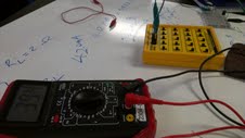
In this lab we learned that in order to have a real inductor a resistor has to be added in series. Using a DMM we measured the resistance in our unknown inductor to be 2 ohms. We applied an AC current in order to determine the capacitance but in order to not damage the equipment we added another resistor to limit the current which was measured at 67.6 ohms. We build the circuit. VIN = 2.88V IIN = 42.3 mA


Computation:
Z = V/I = 72.2
Rext + RL + ZLj
Z = sqrt((Rext + RL)^2 + ZL^2)
w = 2(pi)(1000)
72.2^2 =sqrt(68.9^2+ZL^2) ZL =21.63 ohms = wL L = 3.44*10^-3
wL = 1/wC C= 1/w^2L = 7.36*10^-6 H


Computation:
Z = V/I = 72.2
Rext + RL + ZLj
Z = sqrt((Rext + RL)^2 + ZL^2)
w = 2(pi)(1000)
72.2^2 =sqrt(68.9^2+ZL^2) ZL =21.63 ohms = wL L = 3.44*10^-3
wL = 1/wC C= 1/w^2L = 7.36*10^-6 H
Vppch1 = 2 mV
Vppch2 = 1.5 V
delta t = 10 ms
There is a phase difference 90
|
Frequency (Hz)
|
Vin (V)
|
Iin (mA)
|
Zin (Ω)
|
|
100
|
4.63
|
19.9
|
232.7
|
|
500
|
3.21
|
39.2
|
81.9
|
|
1 k
|
2.96
|
40.6
|
72.9
|
|
5 k
|
2.90
|
38.6
|
75.2
|
|
10 k
|
2.96
|
32.8
|
90.2
|
Tuesday, May 21, 2013
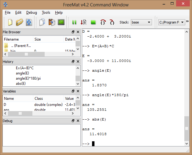
FreeMat Complex numbers
In this lab we learned how to use freemat with complex numbers
Exercise 1
 Exercise 1

Assignment


Exercise 1
Exercise 2
MOSFET
In this lab we use a MOSFET to control the voltage across a motor.
We first connect the motor to the MOSFET and a potentiometer.


We first connect the motor to the MOSFET and a potentiometer.
We observe that the motor does not begin to rotate until around 3.9 V
As we adjust the pot we notice that the motor reacts to the change in voltage that is occurring. It is fairly difficult to make the motor shaft rotate at approximately once per second.
PWM Chopper MOSFET
We replace the pot with a square wave generator set at 10 Khz. We use the oscilloscope to display the waveform of the motor voltage.


Oscilloscope 101
In this lab we practiced using the oscilloscope which will help us measure the voltage and time of a signal based on the wave shape. This instrument will help in future labs.
We first had to get a sign wave to appear on our oscilloscope with a frequency of 5 kHz and amplitude of 5 V. We measured the period to be 210 us, peak to peak amplitude of 10 V, zero to peak of 5 V, and RMS value of 3.53

We then verified these values with the DMM and got VDC = 0 and VAC = 3.36
We then included a DC offset

We then displayed a square function

Mystery Signal: After establishing a steady wave function we measured DC = .03V frequency = 133k Hz and peak to peak amp to be .13 V

We first had to get a sign wave to appear on our oscilloscope with a frequency of 5 kHz and amplitude of 5 V. We measured the period to be 210 us, peak to peak amplitude of 10 V, zero to peak of 5 V, and RMS value of 3.53
We then verified these values with the DMM and got VDC = 0 and VAC = 3.36
We then included a DC offset
adding a 2.5 V offset we attained the values VDC = 2.5 V and VAC = 1.17 V
VDC = 0 V and VAC = 2.6 V
we calculate VAC = sqrt(2.5^2 * 4 * 50ms/ 4 * 50 ms) = 2.5 V
Capacitor Charging / Discharging
In this lab we observed the relations of charging and discharging a capacitor. The relation we see from our equations is that it will essentially never fully charge or discharge as it exponentially approaches either value. With the given knowledge of capacitors we are to construct a circuit from which we determine the thevin values.
We utilize a 9 V DC power supply and determine that C = 62uF from w = CV^2 / 2. There is a charging interval of about 20s with a resulting stored energy of 2.5 mJ and then discharged in 2 s.

Assuming an ideal capacitance we estimate charging resistance to be 64.5 k ohms
Using V = IR we determine the peak current value to be 0.14 mA and P = IV to determine peak power to be 1.26 mW.
The discharging resistance is estimated to be 6.45 k ohms and the peak discharge current and power are 1.4 mA and 12.6 mW respectively.

 charging took about 20 seconds
Graph of discharging capacito

We utilize a 9 V DC power supply and determine that C = 62uF from w = CV^2 / 2. There is a charging interval of about 20s with a resulting stored energy of 2.5 mJ and then discharged in 2 s.
Using V = IR we determine the peak current value to be 0.14 mA and P = IV to determine peak power to be 1.26 mW.
The discharging resistance is estimated to be 6.45 k ohms and the peak discharge current and power are 1.4 mA and 12.6 mW respectively.
We set the power sipply to be 6 V V measured = 5.707 V
VFinal = Vs (RLeak)/(Rc + RLeak) RLeak = 1.256 M ohms
Graph of charging capacitor
Graph of discharging capacito
discharging took about 2 seconds
Questions:
1. Thevenin Values During Charging
RTH = 61.4 k ohms
VTH = 5.707 V
2. Thevenin Values During Disharging
RTH = 6.42 k ohms
VTH = 5.707 V
3. 0.3679 * VF = 3.607 V this occurs around 4s according to our charging waveform
t=RC 4 = R * 62 uF R = 64.5 K ohms
Practical Question:
1. E = V^2 C/2 = 160 mJ = 15kV^2 C / 2 C = 1.4 F
2. C||C + C||C + C||C + C||C = 1.4 F
C = .7
Subscribe to:
Comments (Atom)